Bearing failures
Bearings are small compared to other major motor components, making them particularly vulnerable to damage and wear. It’s no surprise, then, that studies blame more than half of all motor failures on bearing malfunction, most of which result from too little or too much lubrication. The key to avoiding these conditions is to establish a lubrication program using bearing and motor manufacturer guidelines to determine the frequency and amount of lubrication for the motor application, duty (continuous or intermittent), environmental conditions, and bearing size.
Another significant cause of bearing failure is misalignment, the effect of which increases by the cube of the change. For example, an alignment value that is twice the new installation tolerance will reduce bearing life by a factor of 8 (2^3). The solution is simple: align the motor and driven equipment to new or better installation tolerances.
Bearing currents are typically caused by dissymmetry in the motor frame or powering the motor from a variable-frequency drive (VFD). Decades ago, bearing currents were only an issue on very large motors due to their inherent lack of magnetic symmetry. The ubiquitous use of VFDs today, both for new installations and retrofits, subjects these motors to a “chopped” output waveform. The resulting magnetic dissymmetry produces a current path from stator frame to shaft and through the bearings at each end.
Although no solution to bearing currents yet exists, some remedial measures are available. Among the most common of these are insulated bearing housings, ceramic rolling element bearings, and shaft-grounding brushes. Other methods include insulating the shaft bearing journal, installing completely ceramic bearings, and using conductive grease. Applying filters or reactors to the VFD also helps by reducing the magnitude of the bearing current.
Statistically, stator winding failures run a distant second to bearings as a cause of motor failures. Yet the extent of damage, repair cost, and downtime associated with a winding failure is often orders of magnitude greater than for bearing failures.
When it comes to stator windings, mechanical overload is the leading cause of failure. Operating a motor at “only” 15% above rated load (i.e., equal to the 1.15 service factor of many motors) can reduce winding thermal life to one-fourth of normal. A common misunderstanding is that motors can be loaded to their service factor continuously. Actually, service factor capability is intended only for short-term, intermittent use. The solution to mechanical overload is straightforward, but not always easily executed: reduce the load to no more than the power rating of the motor.
Thermal overload results from steady-state electrical causes such as over voltage, under voltage, and unbalanced voltages. A variation in voltage of more than 10% from rated or a voltage unbalance greater than 1% from the average results in excessive heating of the windings. This is another case where the solution is straightforward: bring the voltages at the motor to within tolerance. Implementation can be daunting, however, as it may require special transformers or adjusting the load on each phase.
Electric motors require the ventilation effects of internal and external airflow to extract heat from winding and other component losses. Accumulation of contaminants on the stator windings or externally on the frame and the fan cover (if applicable) may inhibit airflow. Damaged or missing fans also significantly reduce the flow of cooling air. The solution here is to repair or replace damaged or missing fans and to clean the motor. If the motor is an open enclosure in a dirty environment, consider replacing it with a totally enclosed fan cooled (TEFC) model. It’s much easier and faster to remove dirt from the exterior of a TEFC motor than from the inside of an open enclosure motor.
Transient voltages are voltage “spikes” that achieve magnitudes of many times line voltage within microseconds. A single-event transient voltage can occur due to such incidents as lightning strikes, rapid switching of the motor, or utility bus transfers. VFDs, on the other hand, continually produce high-frequency transients due to the “chopped” waveform they use to simulate a variable-voltage and variable-frequency AC supply. The partial discharge (corona) from continuous VFD transients can literally eat away the insulation of the stator winding.
The ideal solution for single-event transients would be to prevent them from occurring. The practical solution is to install transient voltage protection in the motor terminal box. Similarly, the only true solution for repetitive transients from VFDs would be a VFD output without transient voltages. Until that becomes available common preventive measures include installing filters or line reactors and inverter-duty (VFD-rated) motor windings.
Conclusion
Since most motor failures stem from damaged bearings or stator windings, it makes sense to take advantage of relatively simple, straightforward solutions that can prevent premature damage and failure of these components. The reward will be longer, more trouble-free motor life and increased productivity.
Source: http://www.pem-mag.com/Features/Motor-Failures-Common-causes-and-solutions.html
Bearings are small compared to other major motor components, making them particularly vulnerable to damage and wear. It’s no surprise, then, that studies blame more than half of all motor failures on bearing malfunction, most of which result from too little or too much lubrication. The key to avoiding these conditions is to establish a lubrication program using bearing and motor manufacturer guidelines to determine the frequency and amount of lubrication for the motor application, duty (continuous or intermittent), environmental conditions, and bearing size.
Another significant cause of bearing failure is misalignment, the effect of which increases by the cube of the change. For example, an alignment value that is twice the new installation tolerance will reduce bearing life by a factor of 8 (2^3). The solution is simple: align the motor and driven equipment to new or better installation tolerances.
Bearing currents are typically caused by dissymmetry in the motor frame or powering the motor from a variable-frequency drive (VFD). Decades ago, bearing currents were only an issue on very large motors due to their inherent lack of magnetic symmetry. The ubiquitous use of VFDs today, both for new installations and retrofits, subjects these motors to a “chopped” output waveform. The resulting magnetic dissymmetry produces a current path from stator frame to shaft and through the bearings at each end.
Although no solution to bearing currents yet exists, some remedial measures are available. Among the most common of these are insulated bearing housings, ceramic rolling element bearings, and shaft-grounding brushes. Other methods include insulating the shaft bearing journal, installing completely ceramic bearings, and using conductive grease. Applying filters or reactors to the VFD also helps by reducing the magnitude of the bearing current.

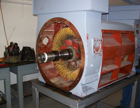
1750 HP electric motor, disassembly and inspection. rmsccolorado.com
Winding failuresStatistically, stator winding failures run a distant second to bearings as a cause of motor failures. Yet the extent of damage, repair cost, and downtime associated with a winding failure is often orders of magnitude greater than for bearing failures.
When it comes to stator windings, mechanical overload is the leading cause of failure. Operating a motor at “only” 15% above rated load (i.e., equal to the 1.15 service factor of many motors) can reduce winding thermal life to one-fourth of normal. A common misunderstanding is that motors can be loaded to their service factor continuously. Actually, service factor capability is intended only for short-term, intermittent use. The solution to mechanical overload is straightforward, but not always easily executed: reduce the load to no more than the power rating of the motor.
Thermal overload results from steady-state electrical causes such as over voltage, under voltage, and unbalanced voltages. A variation in voltage of more than 10% from rated or a voltage unbalance greater than 1% from the average results in excessive heating of the windings. This is another case where the solution is straightforward: bring the voltages at the motor to within tolerance. Implementation can be daunting, however, as it may require special transformers or adjusting the load on each phase.
Electric motors require the ventilation effects of internal and external airflow to extract heat from winding and other component losses. Accumulation of contaminants on the stator windings or externally on the frame and the fan cover (if applicable) may inhibit airflow. Damaged or missing fans also significantly reduce the flow of cooling air. The solution here is to repair or replace damaged or missing fans and to clean the motor. If the motor is an open enclosure in a dirty environment, consider replacing it with a totally enclosed fan cooled (TEFC) model. It’s much easier and faster to remove dirt from the exterior of a TEFC motor than from the inside of an open enclosure motor.
Transient voltages are voltage “spikes” that achieve magnitudes of many times line voltage within microseconds. A single-event transient voltage can occur due to such incidents as lightning strikes, rapid switching of the motor, or utility bus transfers. VFDs, on the other hand, continually produce high-frequency transients due to the “chopped” waveform they use to simulate a variable-voltage and variable-frequency AC supply. The partial discharge (corona) from continuous VFD transients can literally eat away the insulation of the stator winding.
The ideal solution for single-event transients would be to prevent them from occurring. The practical solution is to install transient voltage protection in the motor terminal box. Similarly, the only true solution for repetitive transients from VFDs would be a VFD output without transient voltages. Until that becomes available common preventive measures include installing filters or line reactors and inverter-duty (VFD-rated) motor windings.
Conclusion
Since most motor failures stem from damaged bearings or stator windings, it makes sense to take advantage of relatively simple, straightforward solutions that can prevent premature damage and failure of these components. The reward will be longer, more trouble-free motor life and increased productivity.
Source: http://www.pem-mag.com/Features/Motor-Failures-Common-causes-and-solutions.html
Comments
Post a Comment