One day an engineering lecturer at school discussed an accident at a nuclear power station. Seawater had entered the cooling pipes of the reactor. He asked the students what would happen in such a situation.
A Dean’s Honor-List student answered that neutron flux from the reactor would irradiate the sodium ions in the seawater salt molecules to create a short-lived isotope of sodium. This isotope would emit low-intensity alpha radiation which lodges in the interstices of the ferrous lattices of the steel alloys of the pipes, creating hot spots or fractures, leading to escape of radioactive seawater to the river.
No, the lecturer replied, the pipes will rust.
In troubleshooting, then, it is best to frst suspect the obvious. Why make things more complicated than they really are? Recognizing that there is an overflowing sink and turning off the water, for example, can save a lot of time that might otherwise be spent trying to mop up the floor. To troubleshoot problems, it is necessary to be aware of the various factors that may have a direct influence the situation.
Here is an example: Condensate samples were taken of steam that was being taken from six once through steam generators (OTSGs) and two heat recovery steam generators (HRSGs) to several dozen well pads each with dozens of individual well pads. Each HRSG turbomachine produced 90 MW so a combined 180 MW with some extra headroom reaching 202 MW for peak loading. The HRSGs of oil producing steam assisted gravity drainage (SAG-D) sites make high-temperature, high-pressure steam. But only high-temperature, lowpressure steam is needed to be injected into the ground to liquefy bitumen for extraction, so it ma kes financial sense to run the steam through turbogenerators.
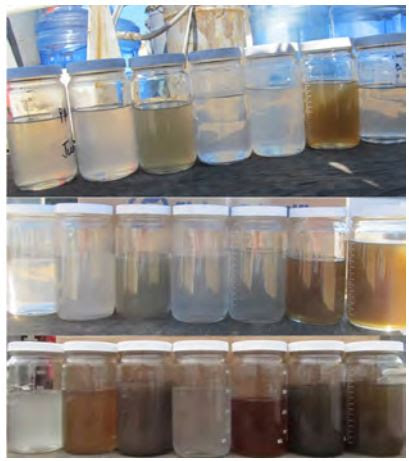
Above ground pipelines carry steam to the pads and above ground pipelines carry the produced bitumen back to the plant. The bitumen is then treated to separate the oil from the water, gasses, and steam. The steam in a SAGD site is injected into the ground; heat and pressures change the viscosity of the heavy oil that is trapped in the sand and it flows downward by gravity to collection pipes and is pumped out. The gasses are collected and burned in the steam generators to create heat to vaporize the recycled water from the wells and reuse it.
When samples of steam condensate samples were collected from the steam being injected into the ground, the high-temperature, low-pressure steam was run through water cooled coils. The samples were analyzed for pH, residual a mines and conductivity and the samples were also run through an Inductively Coupled Plasma Optical Emission Spectrometer (ICP-OAS) for elemental analysis. Samples are burned in a plasma flame that is 2,000°F hotter than the surface of the sun.
The color of steam condensate samples collected varied depending on the well pad, as well as varying from one week to another. Many different tests were run in an attempt to find a statistical correlation between the changing shades. A volatile acid test was done, based on esterification of the carboxylic acids present. All volatile organic acids present are reported as their equivalent mg/L acetic acid. This led to the discovery that the darker the steam condensate, the higher the presence of carboxylic acids (an indication of potential corrosion).
This results from this test can be statistically compared to steam generation parameters such as steam qualities, temperature,pressures, carryover, and amine additions for the set points of the steam engines.
This investigation led to further discoveries. This included the causes of scale taken from samples gathered from boiler pigging operations. X-ray diffraction (XRD) analysis done by an electron microscope scan of scale in an HRSG stream fnal pass going to a turbogenerator. Different kinds of scale have varying effects on heat transfer and metal expansion coefcients, as well as vibration
Orest Protch, retired in 2020, has operated and helped commission many types of process plants including in municipal, industrial and at remote oil camps. He now does freelance writing. For more information, oprotch@gmail.com
Comments
Post a Comment